Alesis Micron Control Knob Encoder Replacement
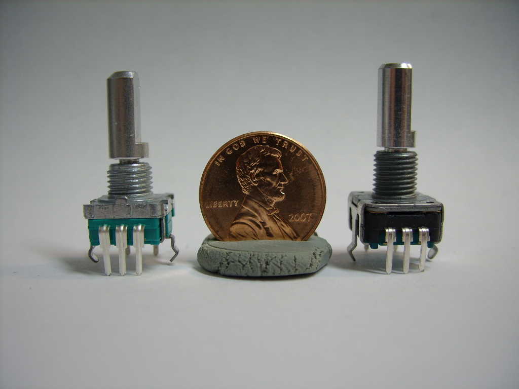
Comparison of the Original and Bourns EncodersBourns manufactures an encoder by the part number of PEC11-4220F-S0024 which is similar enough to the control knob encoder of the Alesis Micron to serve as a replacement. |
|
|
On the left is a replacement encoder which I obtained from
Alesis for $4.00 USD.
You'll have to email their support, who after several days will
forward your email to someone who can help you, who will then ask
that you send your credit card details via unencrypted emails.
I suggest inquiring about paying with a money order.
|
|
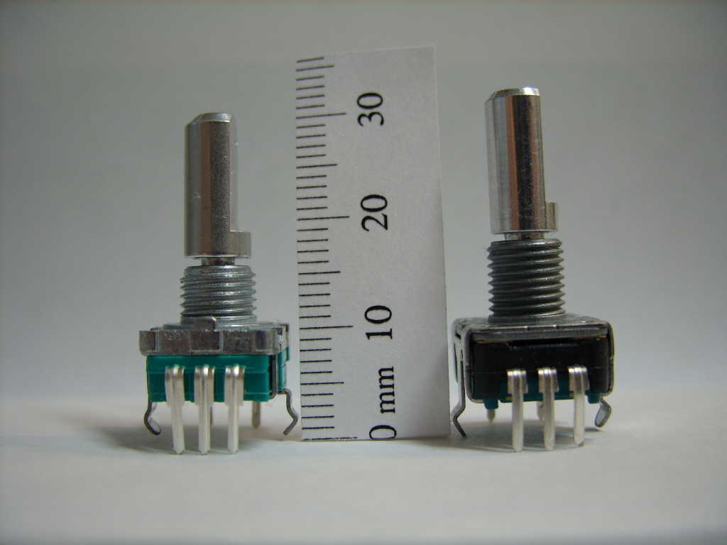
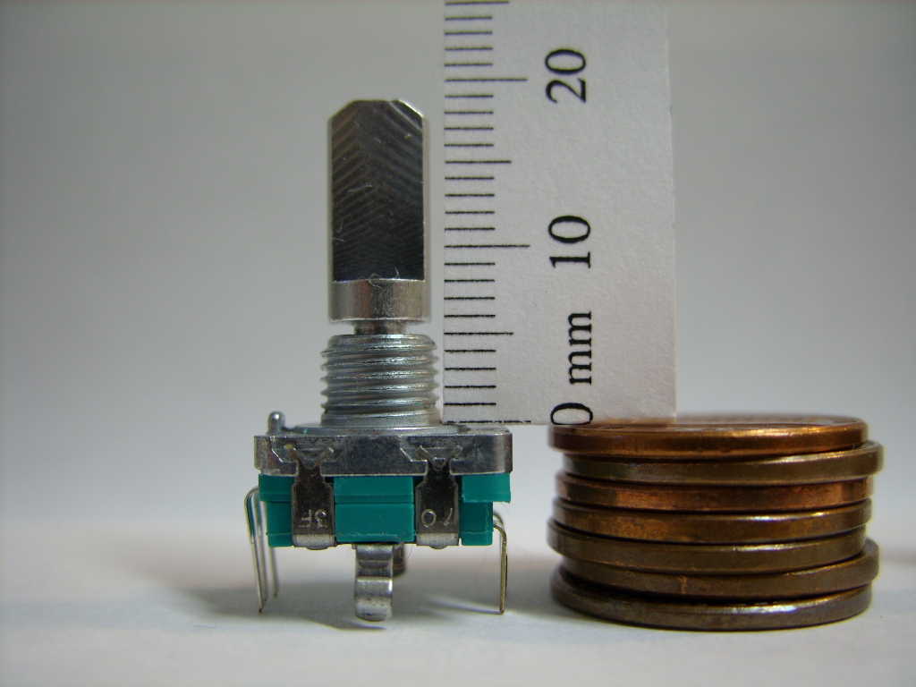
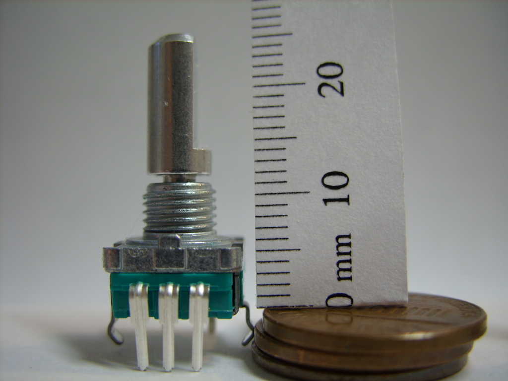
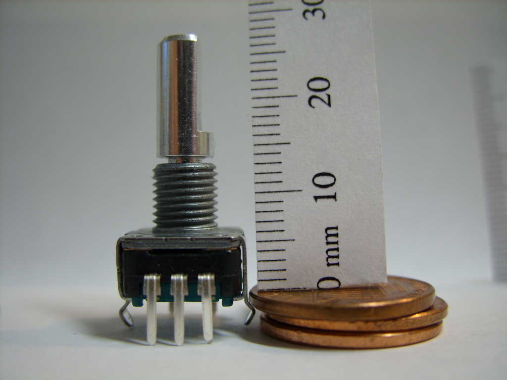
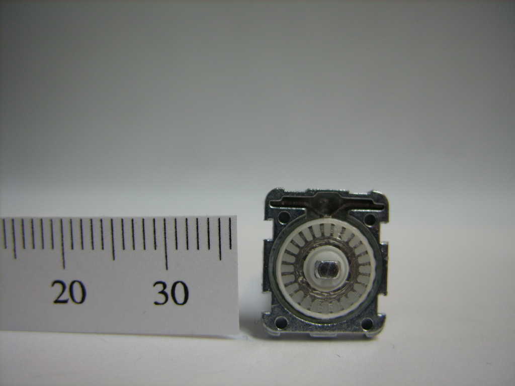
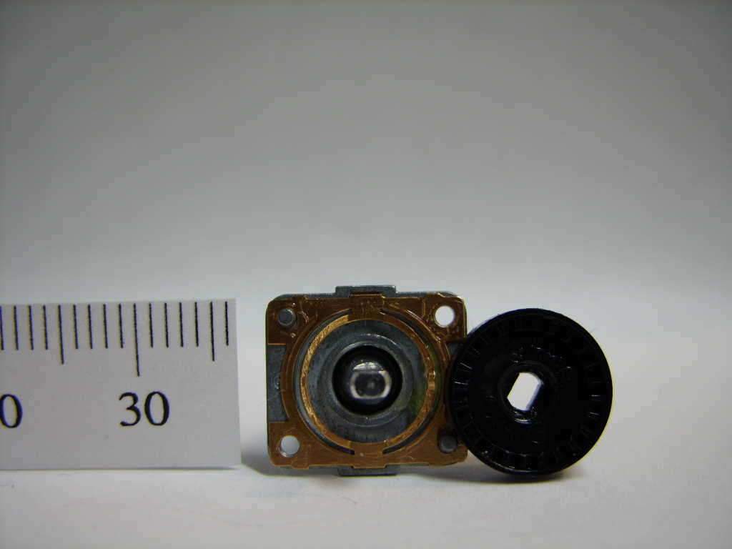
Outside of the U.S., it seems the standard item for size comparison is a ruler, so here are the encoders next to a nice little PDF Printable Ruler. |
| (two more photos showing side dimensions) |
|
When encoders are sold, they're usually described like
"20 mm Rotary Encoder w/ Push Button" or some such.
|
|
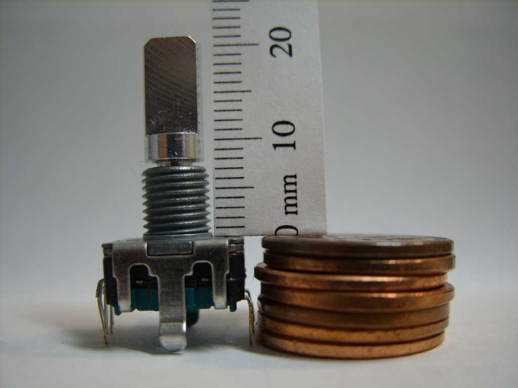
The Bourns replacement is described as a 20 mm encoder, but as you can see here, it is actually 21 mm. |
|
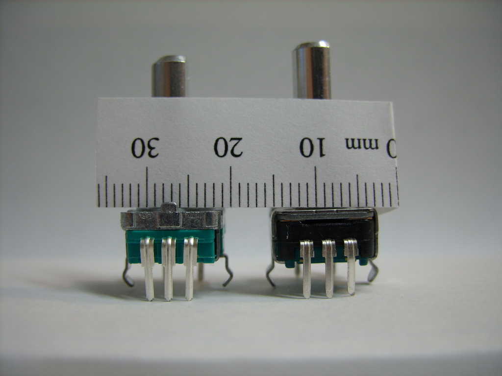
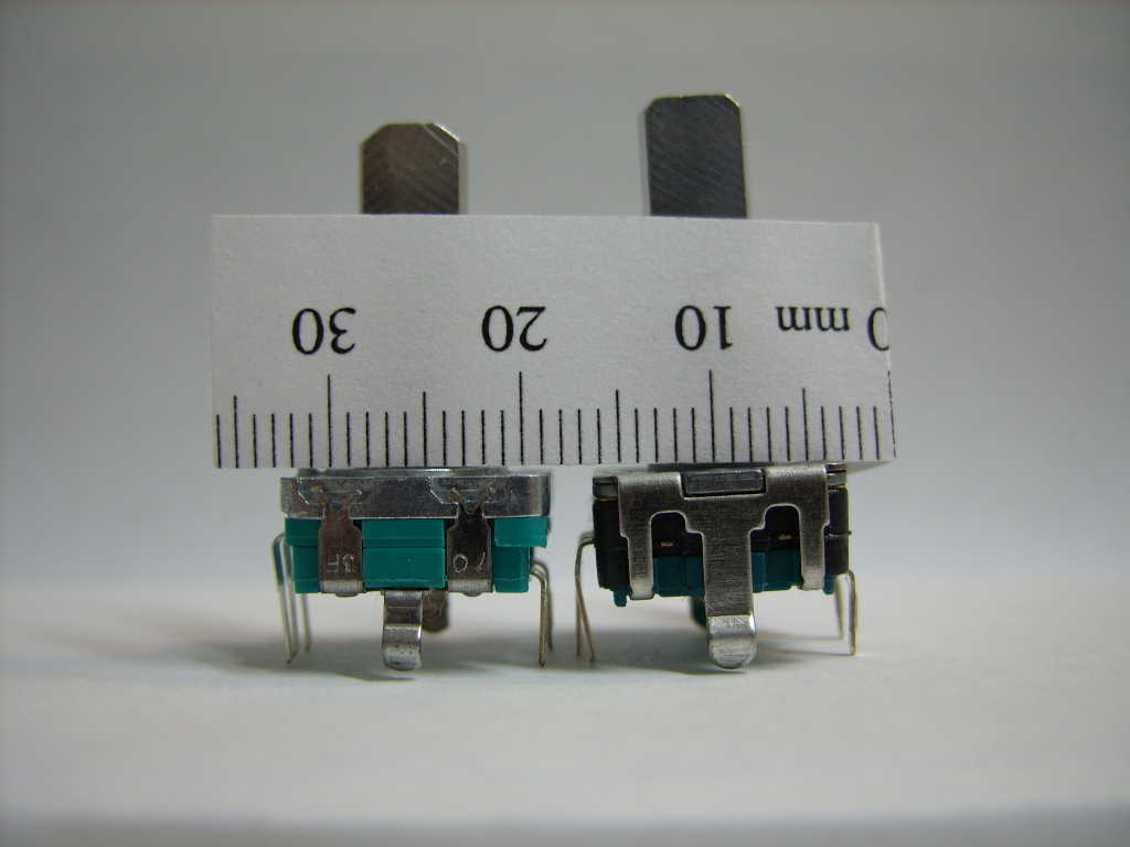
In the Micron, however, the encoder is not bolted to the panel and
so another important dimension is from the bottom of the plastic,
which rests on the circuit board to the top of the main body
of the encoder.
|
|
On the Bourns encoder, this dimension is 7 mm. In total, this makes
the Bourns encoder 3 mm longer than the original encoder.
|

|
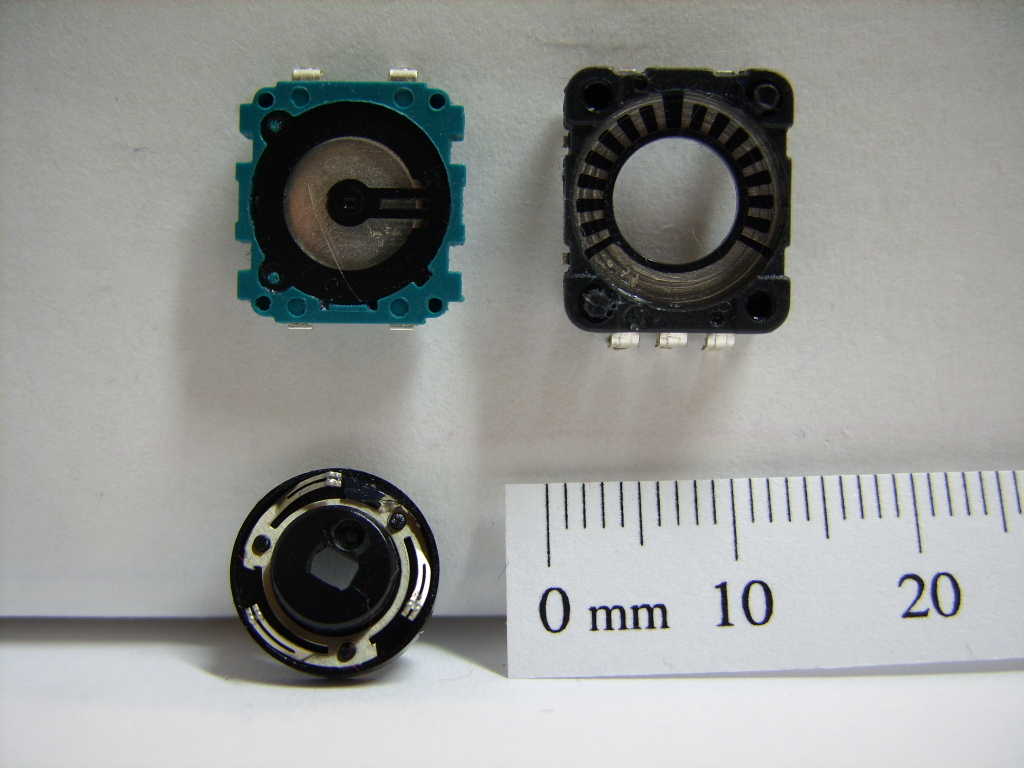
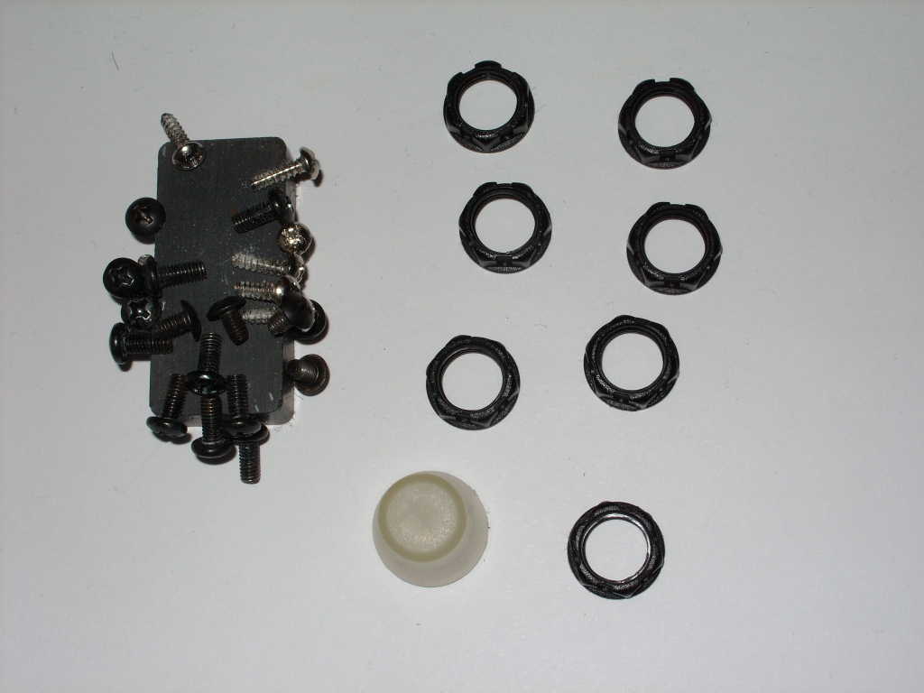
This is a photo of the encoder from Alesis disassembled. The top left piece is the push button. The top right piece contains wipers which connect with the bottom left piece (when flipped over), to form the rotary sensor. |
|
The detent action is created by a steel spring against the side of
the white plastic wheel. The steel spring is difficult to see in
this photo. It is at the top of the piece. It is a flat piece of
steel wire bent in the center to form a point which contacts the
white plastic wheel.
|
|
This is a photo of the Bourns encoder disassembled. The top left piece is the push button. The top right piece contains a pattern which connects with the wipers on the bottom left piece (when flipped over), to form the rotary sensor. |
|
The detent action is created by a copper alloy spring against the
top of the black plastic wheel, which has a series of ridges.
|
The Replacement Process
Replacing this encoder is not an easy task. For someone wishing to
repair their Micron themselves, it will be easier to replace the
entire circuit board that the encoder is attached to rather than
attempt to replace just the encoder. However, if you're going to
replace the circuit board anyway, there's little reason not to
attempt to replace just the encoder first. Unless you seriously mess
up, the worst you'll do is ruin the board and have to replace it,
which you were planning to do anyway. So all you have to lose is
whatever you pay for the new replacement encoder. Also, when you
replace just the encoder, you have the option to replace it with the
Bourns encoder which appears to be more durable. If you order the
entire circuit board from Alesis, it will come with the same encoder
you had before.
|
|
|
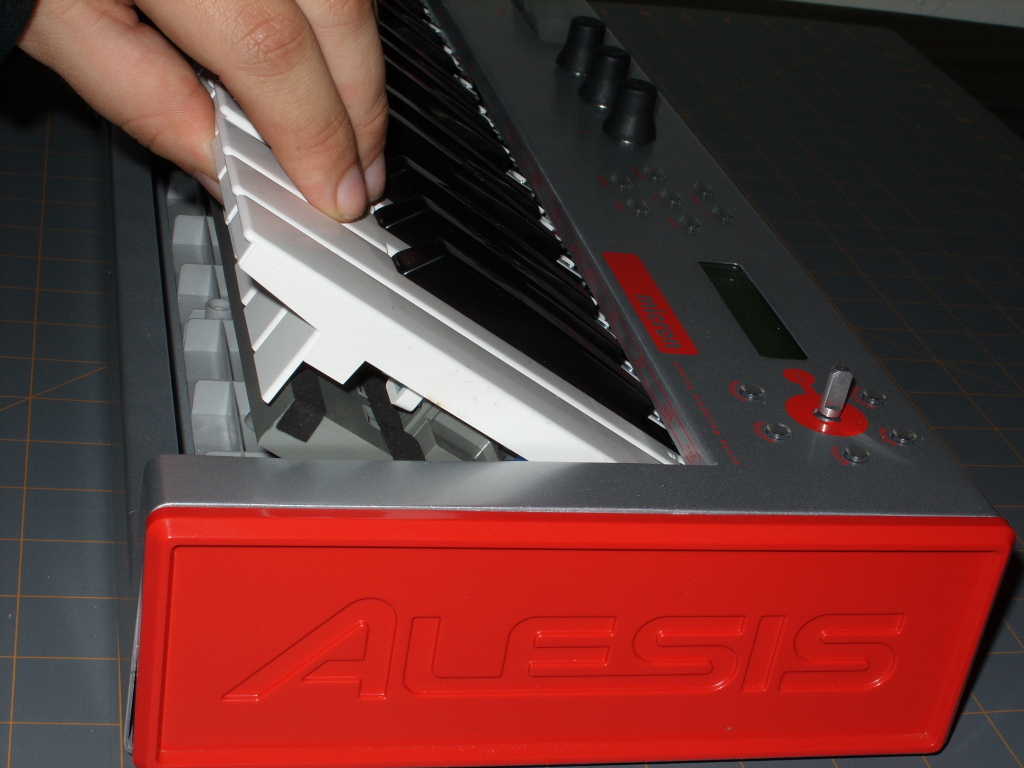
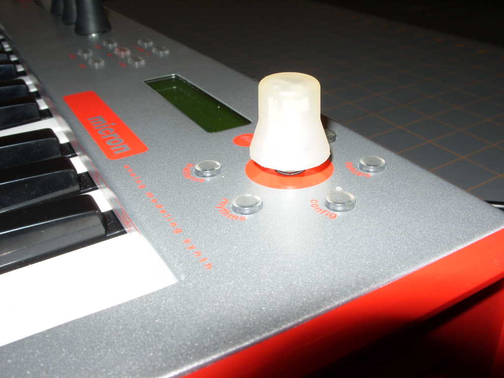
To begin, first remove the control knob from the Micron and set it aside.
To remove it, simply pull on it. It will come off.
|
|
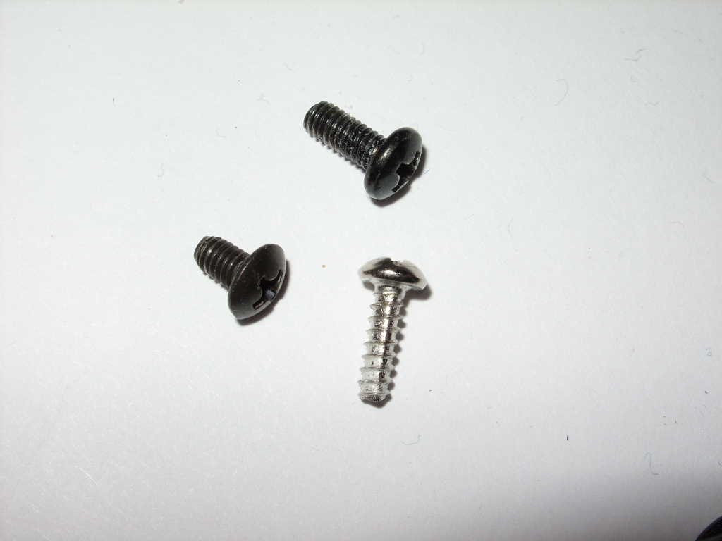
Make sure you've put these things where they will not become lost.
|
|
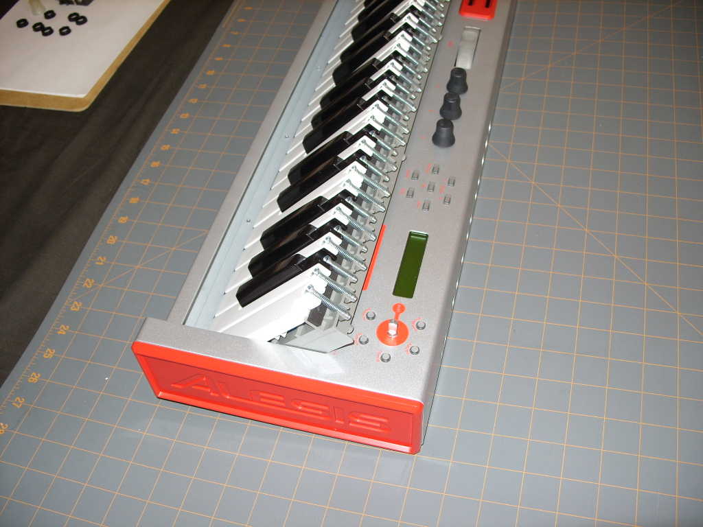
After removing the screws, carefully (keeping in mind that nothing is
holding your Micron together anymore) flip the Micron right side up.
|
|
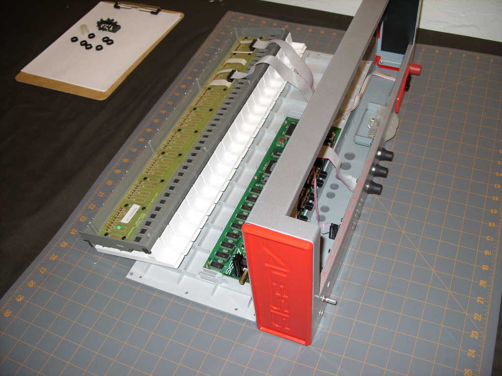
Then set the keyboard down as pictured. This will allow you to flip open the case while leaving the keyboard inside, which is necessary as the cable to the keyboard isn't very long. |
|
This is about the only way you can arrange things with the Micron disassembled. The cables aren't long enough to arrange things more conveniently, and unfortunately, the cables are glued in place. I imagine they could be removed anyway, but I didn't feel like messing with them. |
|
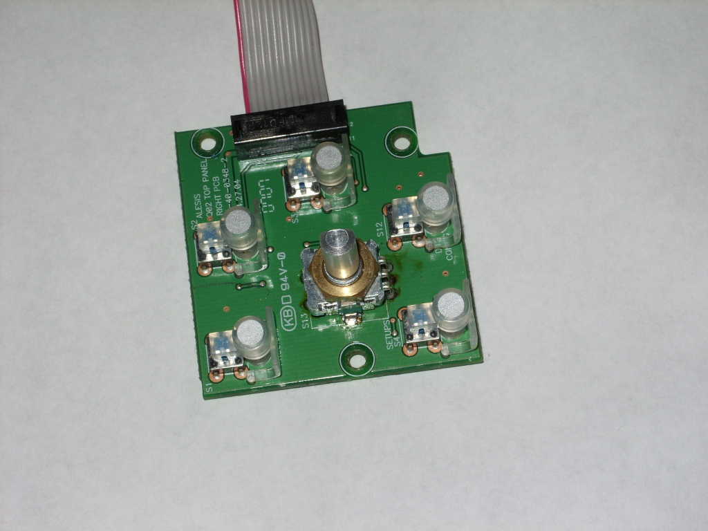
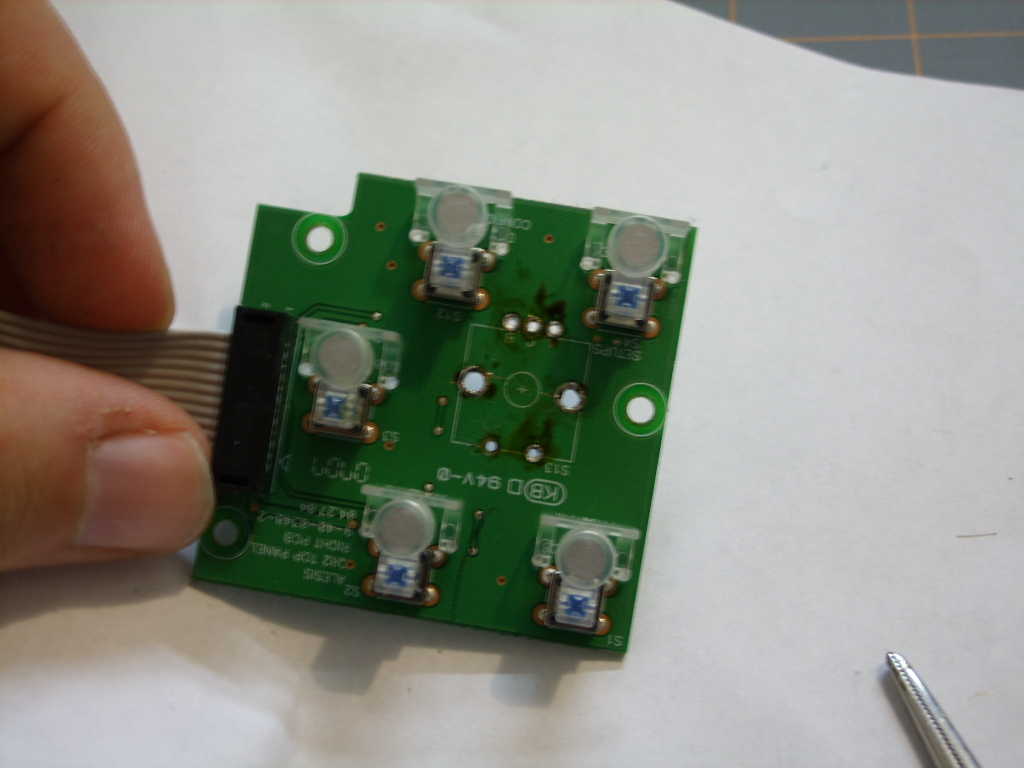
After removing the three screws holding the small board with the
encoder on it, it can be removed and moved slightly away from
everything else.
|
|
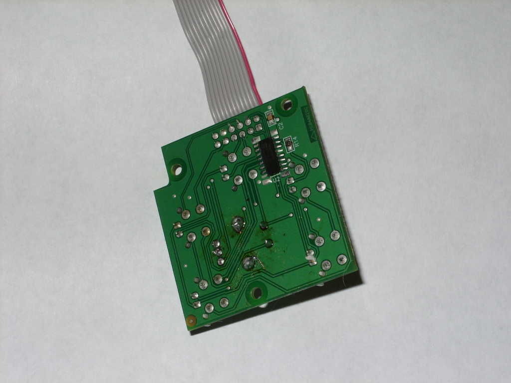
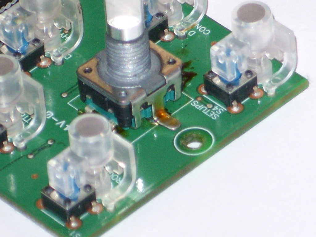
With the old encoder out of the way, remove the pins by grasping them
with pliers on the component side of the circuit board (pictured above)
and pulling them out while heating the solder on the solder side of
the board (pictured at left) with a soldering iron. If done correctly,
the pins should come out with very little force and less than two
seconds of heat from a 30 watt iron. If this doesn't work, pause
to carefully look at everything that might be causing a problem.
You do not want to accidentally damage the board, so use caution.
|
|
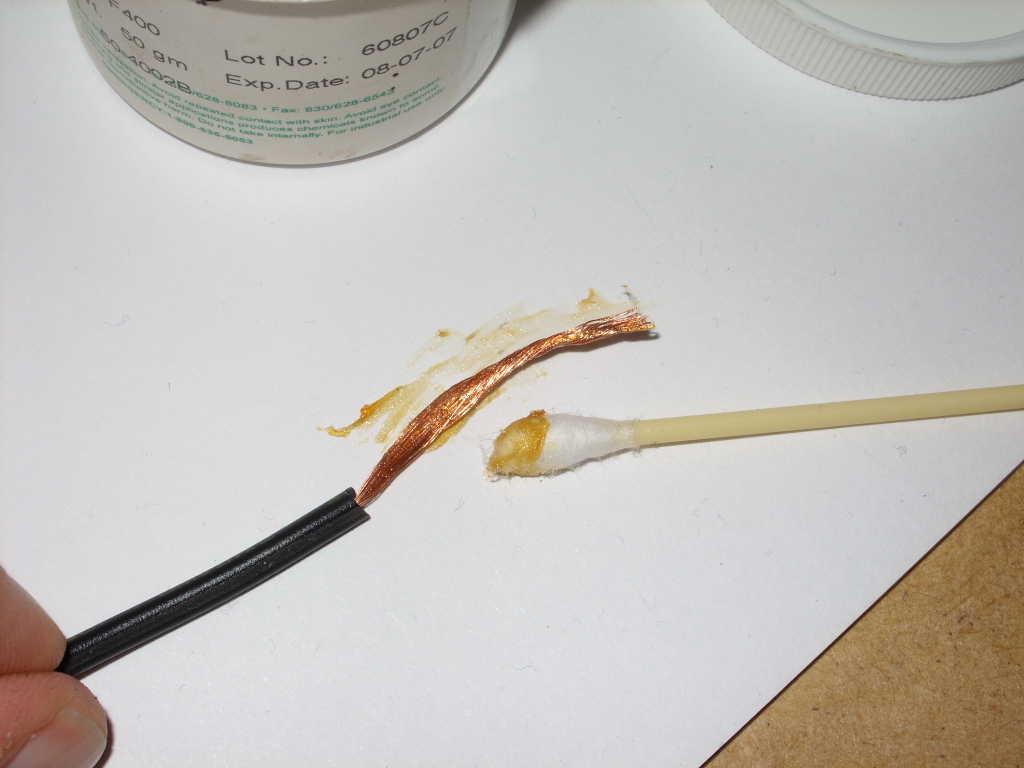
To remove solder, you'll need a solder wick. I make mine out of
stranded wire, as real solder wick is a little too expensive. I like
to use old appliance cord or speaker wire. Strip off a few
centimeters of the insulation, twist the strands together, then
slightly untwist them so that it isn't a tight twist, but the strands
are still held together. Then cover the wire with a
soldering paste or flux.
|
|
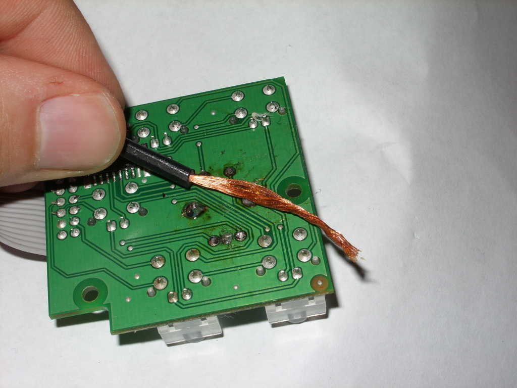
Once you have prepared the solder wick, place it on the solder to be
removed, and heat with the iron. To help the process, lightly
press the iron through the wick into the solder, and twist the wick
back and forth to help the solder flow into it. When the wick is
full, make a new one.
|
|
Once excess solder is removed, you can hopefully use the soldering iron
to push the shorter pins so that they extend out of the component
side of the circuit board, where they can be grasped with pliers
and removed.
|
|
The next step is to insert the new encoder.
|
|
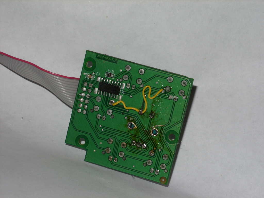
Finally, it's time to fix the problem you created when you
accidentally pulled up that trace. Don't you wish you'd listened to
me when I said to be careful and pause to think when things seem
to require force? I sure wish I had.
|
|
Finally, reassemble the Micron. Be certain not to include any loose
bits of metal within the Micron which may potentially short something
out. Take note to replace the short black screws into the same holes
which they came out of. Do not forget the plastic rings on the back.
|
The Conclusion
Once the Micron is reassembled, the encoder should work perfectly.
At least mine does, and I hope yours will as well. The detent force
isn't as great as with the original part, but as I mentioned above, I
believe this will help to lead to a longer component lifetime.
The push button action of the knob feels better because it moves
downward slightly more and has much more of a click to it.
Also, even when new, the original encoder seemed to occasionally
miss a click when I went from moving in one direction to moving
in the other direction, but the Bourns encoder doesn't seem to have
this problem.
Update!It's been over two years (IIRC), since I replaced the encoder in my Alesis Micron and it still works! That's much better than the few days I got out of the encoder that came with it. Granted, after a month or so with the new encoder I decided that the Micron is a total piece of shit and so I haven't used it much since then, but I'm sure that if I had replaced it with the original part, it would have broken again by now, and so I consider the Bourns encoder a success. Hell, it has out-lasted the pitch wheel, and I don't even use the pitch wheel.Where to Order the EncoderSomeone emailed me to let me know that Newark no longer sells the encoder I purchased.I've found that Digikey continues to sell it, though they're out of stock at the present moment. They claim they'll have more in 28 days just as soon as someone orders one, as they're apparently not planning to order more until then. Given the popularity of this web page, I expect that now that I've linked to them, they'll have more within a month or two and they'll never let them run out of stock again as people will be constantly ordering them. PEC11R-4220F-S0024, the 20 mm version described and photographed above. Digikey also has two other versions of the same encoder, with different shaft lengths. PEC11R-4215F-S0024, a 15 mm version, which may be an ideal substitute as I imagine it would sit at the correct height if one simply tosses a small ball bearing into the knob before inserting the encoder shaft. PEC11R-4225F-S0024, a 25 mm version, which will leave the knob sitting 8 mm too high. This may be ideal if someone would prefer to cut the shaft to the correct length, but that seems like a huge pain in the ass to me, so I don't recommend it. I am vaguely aware that others have since found encoders which fit better into the Micron than the one I used in mine, but despite having a notice here advising people to send me links for years, I have yet to receive a link. If anyone would be so kind as to send me some part numbers I might list them here, particularly if you can report long-term success with the replacement part you used and supply links to web sites where it may be purchased. This is by far the most popular web page on my web site, and so I am sure that many others will appreciate your contribution. |
|