FT240XS Break-Out Board
I've "discovered" a new chip, the
FT240X,
which appears to be much like the FT245R, except that it's the newer version
within FTDI's new line of chips. You can read all about it in
its datasheet.
Basically, it's a USB chip which shows up in your PC as a serial port,
but the data you write to it shows up as a parallel I/O register to your
electronics projects.
Gerber Files
I've created a set of Gerber files for a break-out board for this chip.
You should be able to upload these files (keep them in the ZIP file, upload the ZIP file) to a PCB manufacturer like DirtyPCBs.com who will then send you copies of the board.
Here's what the boards look like:
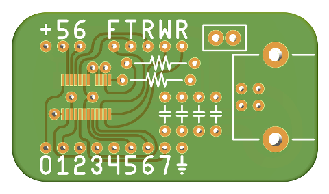
The chip itself obviously goes in the center. Less obviously, pin one belongs at the bottom left, so that the text on the chip matches the orientation of the text on the board.
The circuit design is typical of the many examples within the chip's datasheet. The two resistors are both 27 ohms. The two capacitors in the center are 47 pF. The two capacitors on each side are 100 nF. A typical USB type B connector goes on the right. Above it, two header pins allow for a jumper to supply power from the USB bus to the device, so that the device can easily be configured for either USB-powered or self-powered configuration.
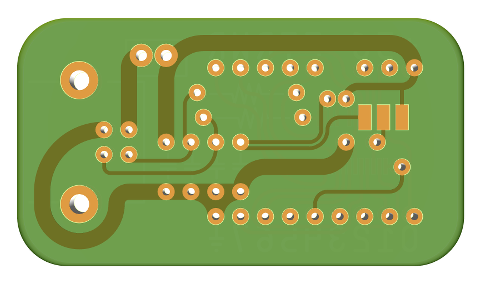
On the back, at center right, is a solder jumper. For 5 volt I/O, connect the middle pad to the pad on the right. For 3.3 volt I/O when the device is powered from 5 volts (like when powered by USB), connect the middle pad to the pad on the left. For 3.3 volt I/O when the device is powered from 3.3 volts (obviously not USB-powered in this case), connect all three pads together.
Power is applied to (or received from, if USB-powered) the top left pin (positive) and the bottom-right pin (ground). The eight pins on the bottom are the data bus, delightfully sorted into numerical order unlike the chip itself. At the top right, the sequence FTRWR represents these signals, all of which are active-low.
Here's what the boards look like:
The chip itself obviously goes in the center. Less obviously, pin one belongs at the bottom left, so that the text on the chip matches the orientation of the text on the board.
The circuit design is typical of the many examples within the chip's datasheet. The two resistors are both 27 ohms. The two capacitors in the center are 47 pF. The two capacitors on each side are 100 nF. A typical USB type B connector goes on the right. Above it, two header pins allow for a jumper to supply power from the USB bus to the device, so that the device can easily be configured for either USB-powered or self-powered configuration.
On the back, at center right, is a solder jumper. For 5 volt I/O, connect the middle pad to the pad on the right. For 3.3 volt I/O when the device is powered from 5 volts (like when powered by USB), connect the middle pad to the pad on the left. For 3.3 volt I/O when the device is powered from 3.3 volts (obviously not USB-powered in this case), connect all three pads together.
Power is applied to (or received from, if USB-powered) the top left pin (positive) and the bottom-right pin (ground). The eight pins on the bottom are the data bus, delightfully sorted into numerical order unlike the chip itself. At the top right, the sequence FTRWR represents these signals, all of which are active-low.
F: The "SIWU#" pin, which flushes data in the FIFO to the PC immediately.
T: The "TXE#" pin, which indicates when data may be written to the FIFO.
R: The "RXE#" pin, which indicates when data is available to be read from the FIFO.
W: The "WR#" pin, which writes data into the FIFO to be sent to the PC.
R: The "RD#" pin, which reads data from the FIFO which came from the PC.
The other pins labeled 5 & 6 are the "CBUS5" and "CBUS6" pins,
the exact function of which is configurable via USB using a utility from
FTDI, but by default you can simply ignore them. The SIWU# pin (the one
labeled "F") may also be ignored if you don't care to utilize it.
T: The "TXE#" pin, which indicates when data may be written to the FIFO.
R: The "RXE#" pin, which indicates when data is available to be read from the FIFO.
W: The "WR#" pin, which writes data into the FIFO to be sent to the PC.
R: The "RD#" pin, which reads data from the FIFO which came from the PC.
Update!
I created a new version of the board described above, both in order to
provide a little more room above and below it when it is placed on
solderless breadboard, and to have "left" and "right" versions, where
the USB connector is on opposite sides of the board, and to get two
copies of the board in a 5 cm × 5 cm board, so that I can get 20 copies
from DirtyPCBs for only $14.
Here are the Gerber files and this blog post has some pictures. Until I get around to writing a better update to this page, I'll just say that, like the design described above, there's a "solder jumper" on the back, consisting of two large pads and one small pad that are freakishly close together. Connect the tiny pad to the lower large pad for 5 volt I/O, or to the higher large pad for 3.3 volt I/O, or connect all three pads together for 3.3 volt I/O when the chip is itself powered by 3.3 volts. Also, the two 47 pF capacitors go near the USB connector, and the two 100 nF capacitors go in the other two positions.
Here are the Gerber files and this blog post has some pictures. Until I get around to writing a better update to this page, I'll just say that, like the design described above, there's a "solder jumper" on the back, consisting of two large pads and one small pad that are freakishly close together. Connect the tiny pad to the lower large pad for 5 volt I/O, or to the higher large pad for 3.3 volt I/O, or connect all three pads together for 3.3 volt I/O when the chip is itself powered by 3.3 volts. Also, the two 47 pF capacitors go near the USB connector, and the two 100 nF capacitors go in the other two positions.
Historical Timeline
The rest of this web page documents the timeline of having the board manufactured by DirtyPCBs,
which I leave here simply because, when I ordered the boards myself, I was wondering what the
experience was going to be like, but didn't find much on the internet about it. So, if you're
wondering, here's what the process is like...
April 15, 2015
I ordered the boards from
dirtypcbs.com, who is able to
send about 10 copies for a mere $14, if you can wait "1-8+ weeks."
Given my lack of desire to spend a lot of money on something that may
not even work, I elected for the inexpensive $14 service, and thus it
may be two months before I receive the boards.
April 20, 2015
DirtyPCBs.com sent me an email to let me know that the
board house rejected my PCB design because "gerber is empty."
Obviously the files aren't empty. If they were empty, where did that
awesome 3D rendering above come from?
To try to resolve this issue, I guessed that they may be taking issue with the end-of-line characters being just LF rather than CRLF. So I changed them to CRLF. Also, since every example Gerber I've seen begins with a comment, I added a G04 comment to the beginning of the files just in case they're looking for that as a sort of "magic number" to identify the file type. Neither change matters according to the RS-274X specification, but since the files already comply with that specification, I have no clue what to do other than make nonsense changes in hope of stumbling upon whatever it is that their Gerber software is having an issue with, given that they don't see fit to let me know what that is.
I also tried an online DFM test, which similarly rejected the files, telling me that they are not in Gerber format. It's amusing that the files display just fine in many Gerber viewers, but no manufacturer is able to read them. After sending them the new version with CRLF line terminators, they then merely complained about the lack of an NC drill file. So I created an NC drill file as well, in addition to the existing Gerber drill file, and sent them the NC drill file instead. Then they once again told me that the files are not in Gerber format.
Well, fuck...
Anyway, I found another DFM test, and after it told me to downgrade the files from version 2 to version 1, it finally accepted them. Hooray!
So here's the two versions I presently have:
gerbers-with-nc-drill.zip
gerbers-with-gerber-drill.zip
Assuming that DirtyPCBs' FAQ may be mistaken in suggesting that I send a Gerber drill file, I've uploaded the NC drill file version. I expect at least two days before I discover if they accept it, as they will have to send it to the board house, and the board house reject it again. If nothing else, no other manufacturer seems to want Gerber drill files, they all ask for NC drill files, so perhaps they at least know how to read NC drill files and can utilize them instead of Gerber drill files, assuming they honestly intended to ask for Gerber drill files rather than, as I assume, the FAQ was written by someone without much knowledge as to what the files contain, and so they just refer to any set of PCB files as a set of Gerber files.
Indeed, that seems to be the whole problem with Gerber files. It's a very loose specification capable of containing data in a lot of formats. ...but people are all like "just specify Gerber files" much like one might decide to "just buy a toaster" and end up with a 240 volt toaster that is unable to produce toast in their 120 volt house, not that that matters since what they bought wasn't intended to toast bread anyway.
I shall keep this page up-to-date with progress information, even though I imagine no one is watching it.
April 21, 2015
Given that Digikey's shipping doesn't require 1 to 8 weeks, needless to say I received the FT240XS chips days ago.
Anxious to discover how well they work, I did my best to produce my PCB design on my own, and ended up with this:
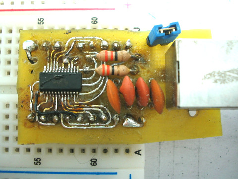
It may be in the running for the ugliest PCB ever created, but the damn thing works.
I didn't have any 27 Ω resistors, so I sustituted 33 Ω, and of course the back is un-etched and simply connected with soldered wires, which is far easier to do than creating a PCB, never mind a double-sided PCB. I wouldn't bother with a damn PCB at all if I could just get the chip in DIP packaging.
Anyway, I tested it in my Z80 EEPROM programmer and also into a simple logic analyzer I built, and in neither case did I have to modify the software at all aside from pointing it to the new /dev/ttyUSBx device. So it not only works, but it's a perfect substitution for the more expensive FT245R.
Now, can I get anyone to manufacture the damn board?
Anxious to discover how well they work, I did my best to produce my PCB design on my own, and ended up with this:
It may be in the running for the ugliest PCB ever created, but the damn thing works.
I didn't have any 27 Ω resistors, so I sustituted 33 Ω, and of course the back is un-etched and simply connected with soldered wires, which is far easier to do than creating a PCB, never mind a double-sided PCB. I wouldn't bother with a damn PCB at all if I could just get the chip in DIP packaging.
Anyway, I tested it in my Z80 EEPROM programmer and also into a simple logic analyzer I built, and in neither case did I have to modify the software at all aside from pointing it to the new /dev/ttyUSBx device. So it not only works, but it's a perfect substitution for the more expensive FT245R.
Now, can I get anyone to manufacture the damn board?
April 27, 2015
DirtyPCBs.com sent me an email to inform me that they have shipped the boards. I wish they would have sent a photo or something, as I'm curious whether I got holes or not, but I guess I can't expect much for only $14.
I'll just have to wait "1-8+ weeks" to find out, which I guess means I should receive them between May 4 and June 22, or, if that "+" comes into play, perhaps not until next year.
I'll just have to wait "1-8+ weeks" to find out, which I guess means I should receive them between May 4 and June 22, or, if that "+" comes into play, perhaps not until next year.
May 18, 2015
The boards have arrived!
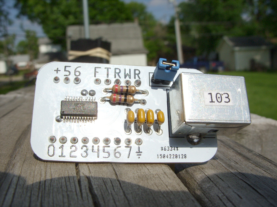
I'll spare you the unboxing photos, mostly because I didn't care to take them. ...and, for that matter, to hell with photos of the bare PCBs too. Instead, here's what it looks like with all of the parts mounted:
I received 12 boards, complete with my weird curvy traces and fancy rounded corners. ...and holes, I got holes!
As stated elsewhere on the internet, the solder mask is a bit off on some of the boards, but thankfully I expected that and added an additional 2 mills of clearance to the solder mask. There's also the small numbers on the bottom right that they added in order to identify which boards were mine, as they mention in their FAQ. Overall I'm quite bloody happy with these boards.
Wanting to see the traces underneath more easily, I soaked one of the boards in acetone for an hour hoping to dissolve the solder mask, but whatever it is made out of, it's chemically sound. Both it and the silkscreen were unharmed. So there's zero concern about the silkscreen or solder mask being removed by washing flux away with isopropyl alcohol.
If I send these off to be made again, I may make a few changes. The most important is that the board is so large that when you place it on solderless breadboard, you're forced to choose between wires barely fitting above it, or barely fitting below it. So cutting 50 mills from the top and bottom would be a good idea. There probably also shouldn't be so much pad around the holes for the header pins. I'd also look into panelizing the design, so that each 5x5 cm PCB contains two copies instead of just one, so that I'd get 20 boards for the price of 10. Most PCB manufacturers won't allow you to do that, but the manufacturer DirtyPCBs.com uses is one of the rare ones that will allow it.
This is what each completed board costs:
Anyway, I'm just hopelessly amused that I can do something like this without the PCB even being the most expensive component, nevermind the situation a decade ago when the PCB would have cost 10x all of the other components combined. I just wish I could get the boards in a few days rather than in a few weeks.
I'll spare you the unboxing photos, mostly because I didn't care to take them. ...and, for that matter, to hell with photos of the bare PCBs too. Instead, here's what it looks like with all of the parts mounted:
I received 12 boards, complete with my weird curvy traces and fancy rounded corners. ...and holes, I got holes!
As stated elsewhere on the internet, the solder mask is a bit off on some of the boards, but thankfully I expected that and added an additional 2 mills of clearance to the solder mask. There's also the small numbers on the bottom right that they added in order to identify which boards were mine, as they mention in their FAQ. Overall I'm quite bloody happy with these boards.
Wanting to see the traces underneath more easily, I soaked one of the boards in acetone for an hour hoping to dissolve the solder mask, but whatever it is made out of, it's chemically sound. Both it and the silkscreen were unharmed. So there's zero concern about the silkscreen or solder mask being removed by washing flux away with isopropyl alcohol.
If I send these off to be made again, I may make a few changes. The most important is that the board is so large that when you place it on solderless breadboard, you're forced to choose between wires barely fitting above it, or barely fitting below it. So cutting 50 mills from the top and bottom would be a good idea. There probably also shouldn't be so much pad around the holes for the header pins. I'd also look into panelizing the design, so that each 5x5 cm PCB contains two copies instead of just one, so that I'd get 20 boards for the price of 10. Most PCB manufacturers won't allow you to do that, but the manufacturer DirtyPCBs.com uses is one of the rare ones that will allow it.
This is what each completed board costs:
  $2.1600 - one FT240XS
  $1.6667 - one of the 12 PCBs I received
  $0.3632 - one USB type B connector
  $0.2352 - two 47 pF capacitors
  $0.1968 - two 100 nF capacitors
  $0.0580 - one two-pin header jumper
  $0.0438 - two 27 ohm resistors
  $0.0329 - one two-pin header connector
  ======================================
  $4.76 - Total
That's minus the cost of solder, the wire I used for the 17 pins that connect to the solderless breadboard, and my time. ...but it's obviously way better than $23.75 for those hideously-overpriced development boards.
Anyway, I'm just hopelessly amused that I can do something like this without the PCB even being the most expensive component, nevermind the situation a decade ago when the PCB would have cost 10x all of the other components combined. I just wish I could get the boards in a few days rather than in a few weeks.
So...
Send comments and questions to my email address.
Also, just in case anyone might ever search for something like this, I feel the need to mention that one might refer to this chip as the FT240, the FT240X, or the FT240XS, and that they might refer to a PCB such as this as a "break out board," a "break-out board," or even a "breakout board." So many possibilities! It's a shame that search engines don't pay attention to keywords meta-tags anymore, as that'd be the perfect place to put this garbage, but they don't, and so instead it's here, and it looks tacky as all fuck. ...but, oh well, probably no one reads the bottom of web pages anyway.
Also, just in case anyone might ever search for something like this, I feel the need to mention that one might refer to this chip as the FT240, the FT240X, or the FT240XS, and that they might refer to a PCB such as this as a "break out board," a "break-out board," or even a "breakout board." So many possibilities! It's a shame that search engines don't pay attention to keywords meta-tags anymore, as that'd be the perfect place to put this garbage, but they don't, and so instead it's here, and it looks tacky as all fuck. ...but, oh well, probably no one reads the bottom of web pages anyway.