I found some pictures of Z80 computers I build in the past the other day. I'll post them all.
This might be the first one that I ever built, I'm not entirely sure.
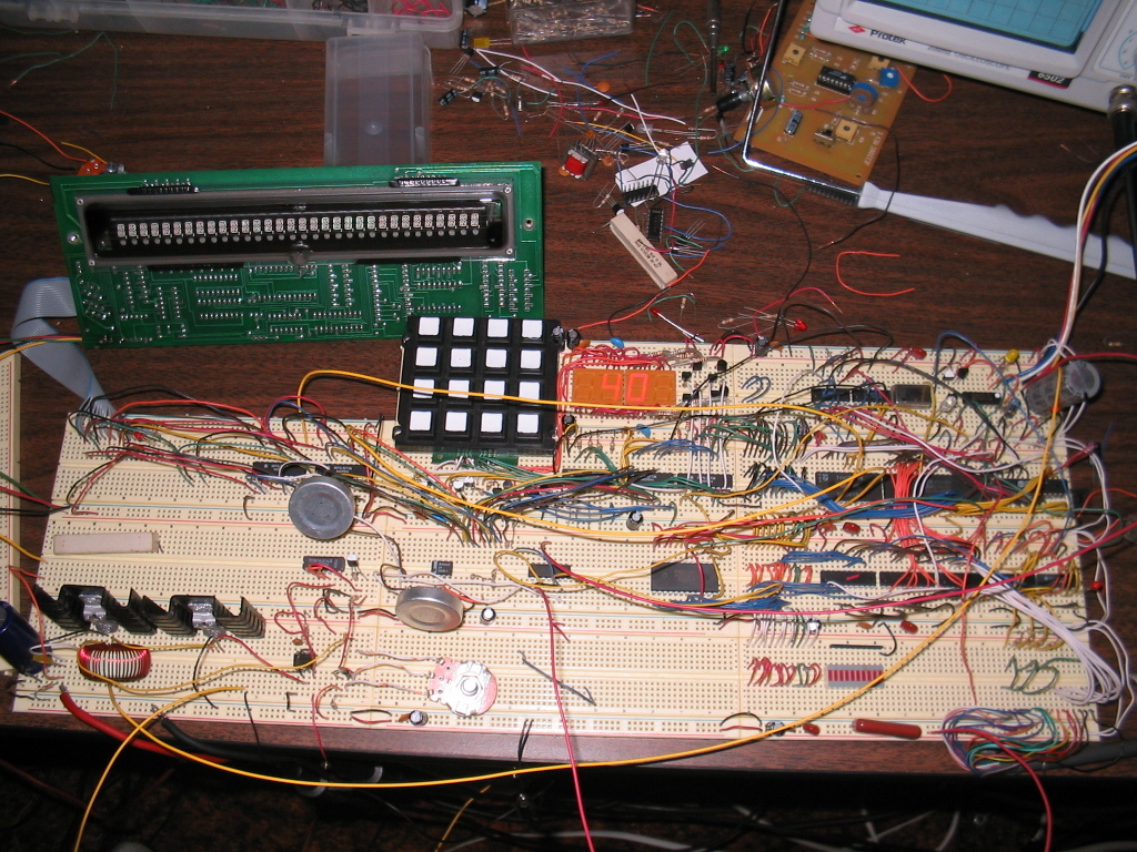
Here's a later one, after I gave up on using colors to differentiate anything. I just cut all of my jumper wires to various lengths and every other length is the opposite color, which helps to distinguish similar lengths.
Both of those used something similar to my EEPROM burner to program them, except that this was before I had those FTDI chips, so this was done over a parallel port instead.
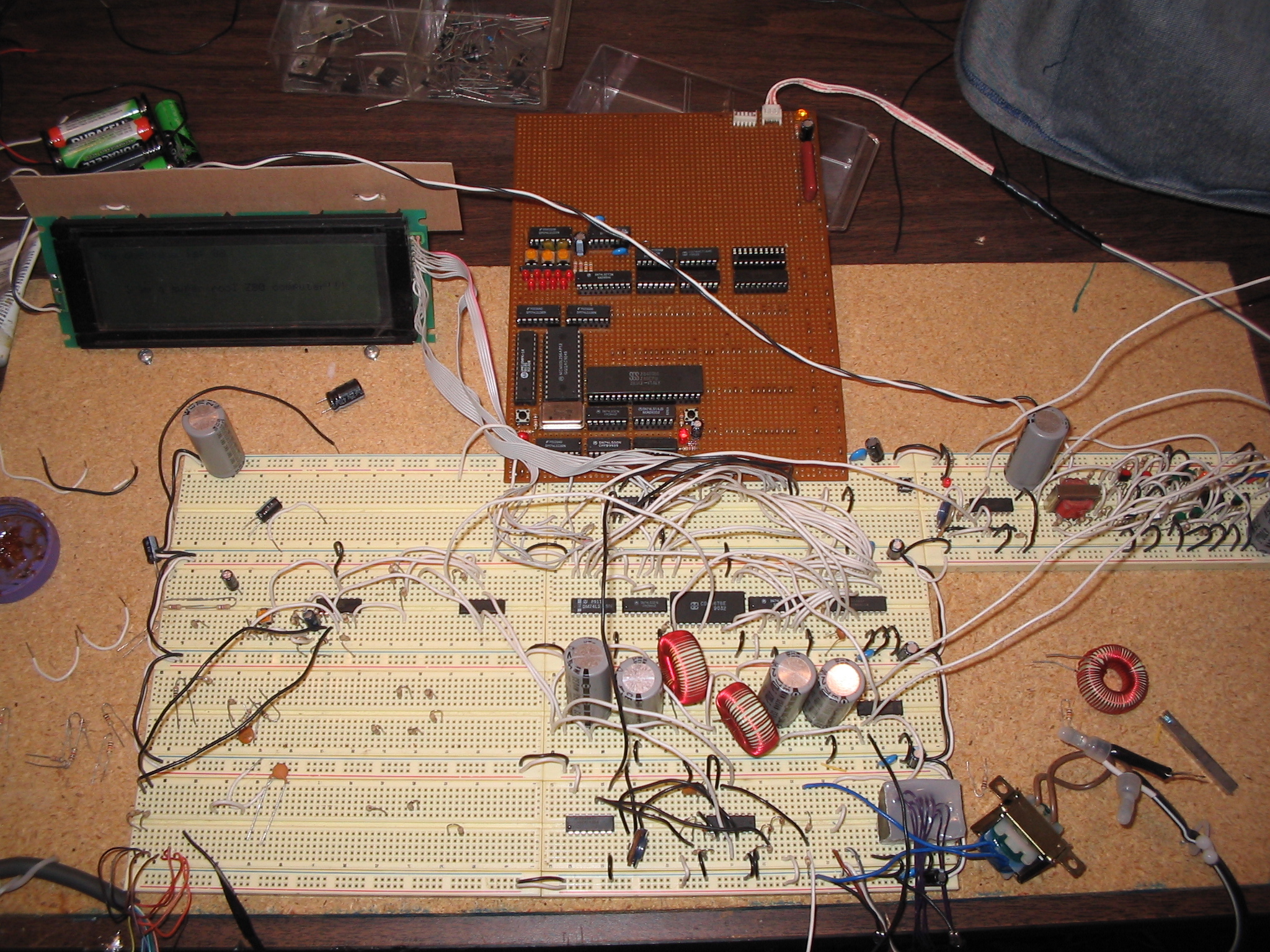
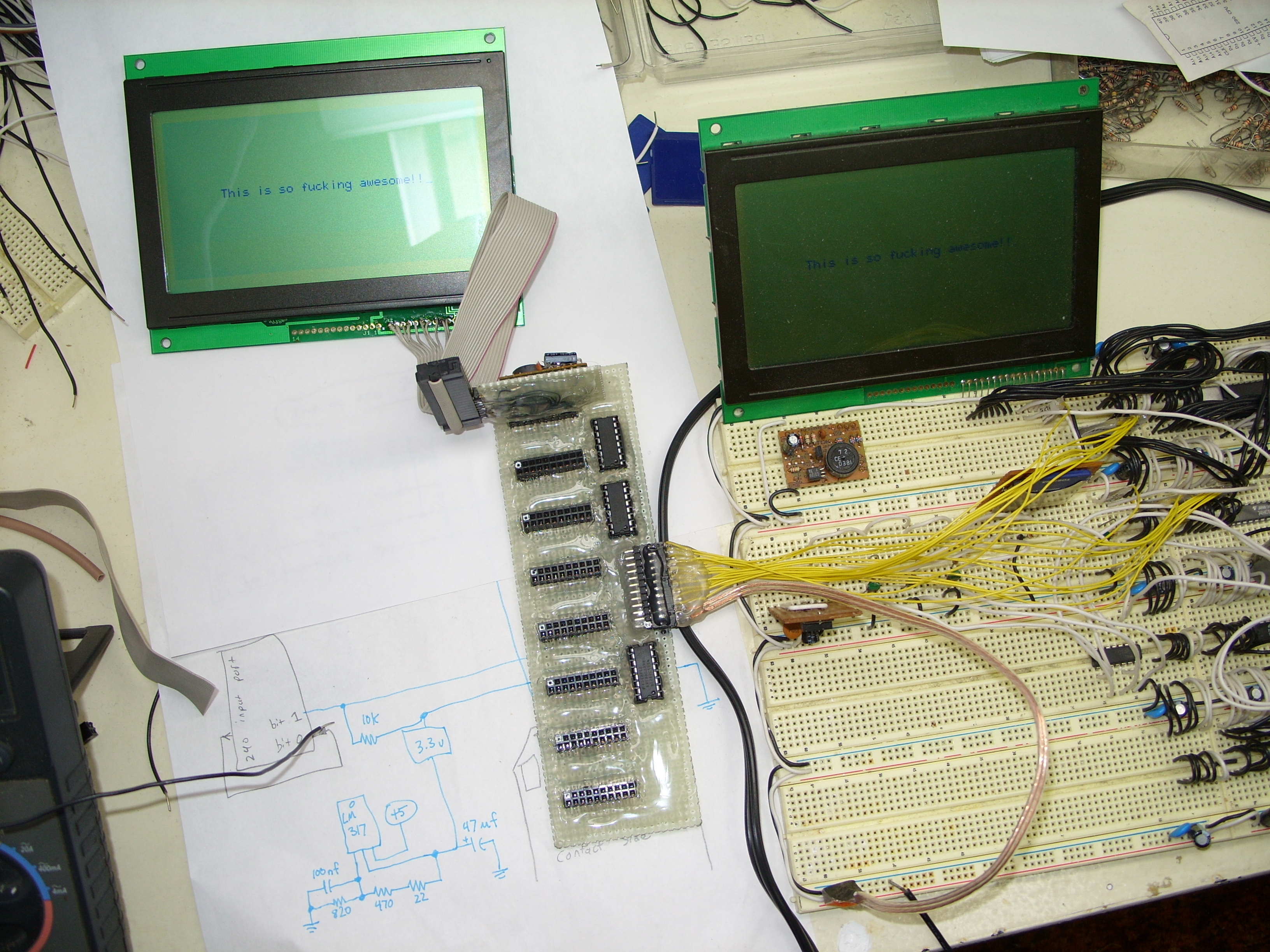
I later build the circuit in more permanent form on some prototype board. With this one I switched from using a parallel port to a serial port, using a somewhat complicated circuit that would de-serialize the bytes from the serial port and similarly use the Z80's HALT signal to pause it until the next byte was available. There was no way for the computer to read back data though, which is why the LCD displays the checksum: So I could look at it and verify that it was programmed correctly. It quite often wasn't.
This is the same one from a different angle, and with something (IDK what) built on the solderless breadboard. The end of the prototype board has wires that poke down into the solderless breadboard to make connections.
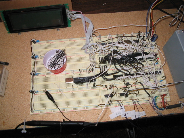
This one shows early testing of the "bus board." This was before any "CPU board" had been built, so that was on solderless breadboard.
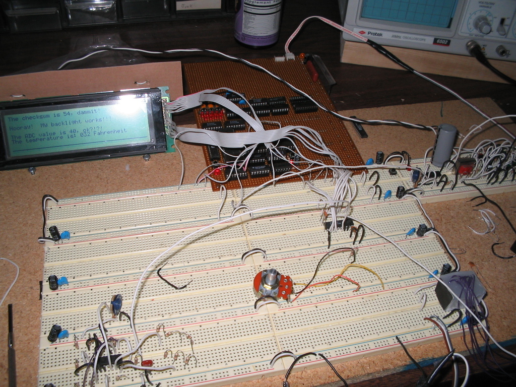
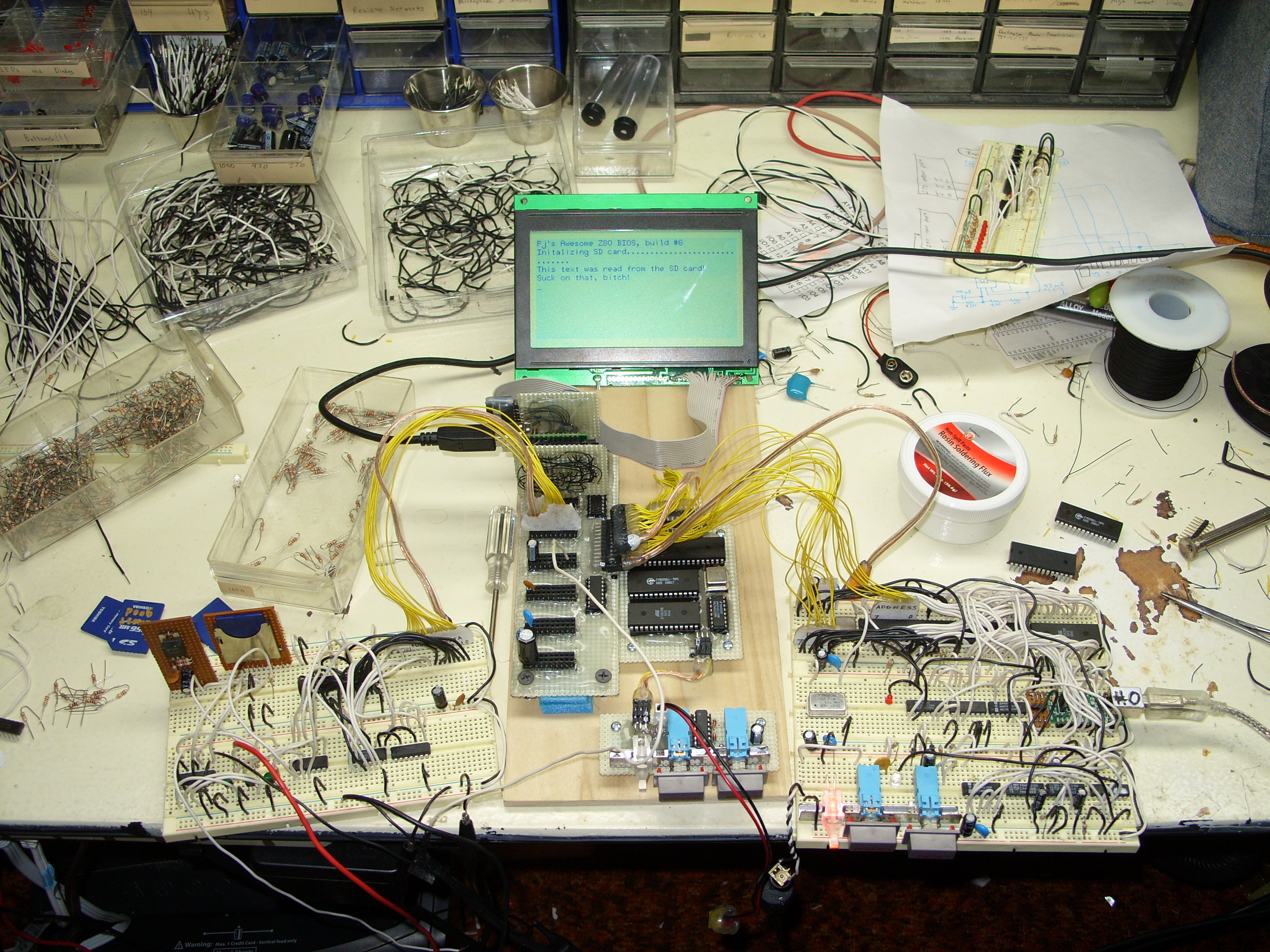
This is later when I had made the CPU board as well, but in this picture it's still connected to the CPU on solderless breadboard as there I've built the EEPROM burner circuit (with USB this time). On the left is a prototype SD card reader circuit, and the LCD indicates I was testing boot from SD card.
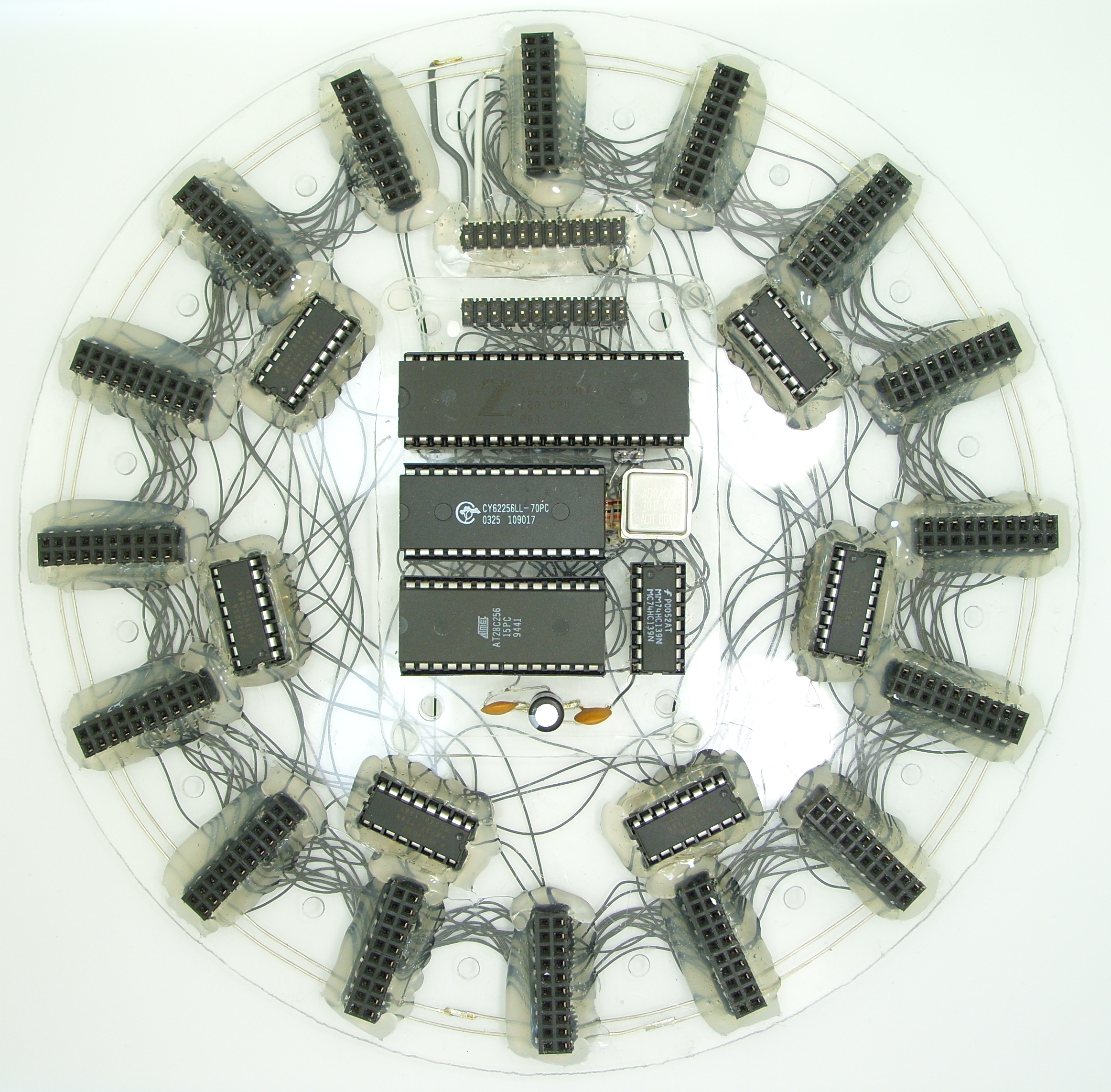
Later I switched from using prototype board to acrylic glass, as acrylic glass is cheaper.
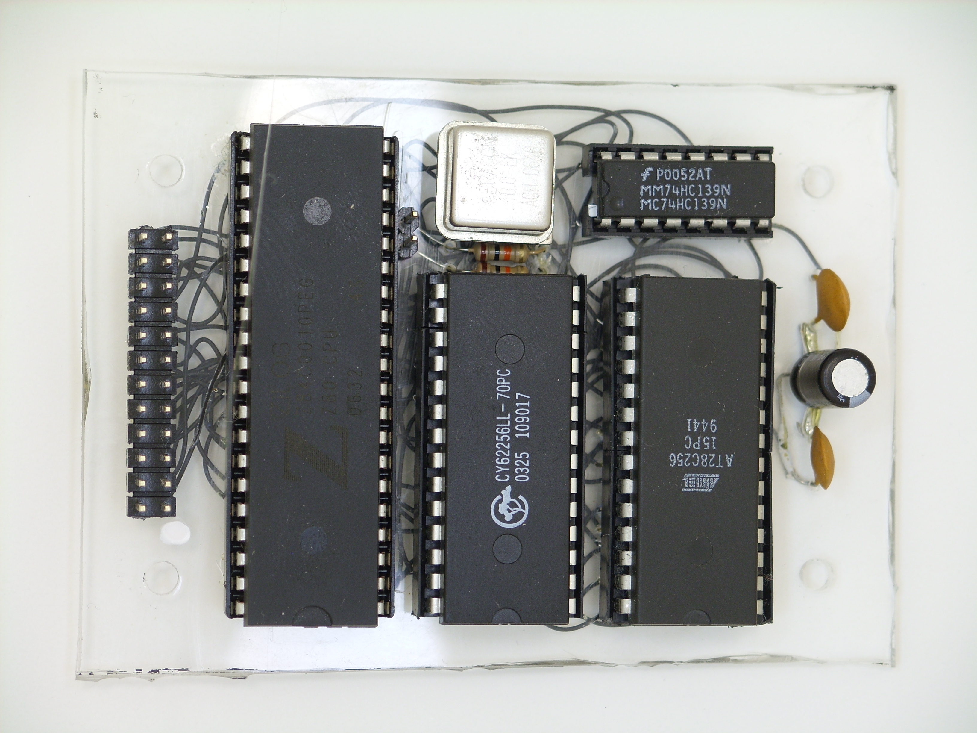
It also kind of conveniently lets you see what everything is soldered to.
Here is the above CPU board in the center of what I call my "bus window" because it's made of glass, whereas a bus board would be made of wood, right?
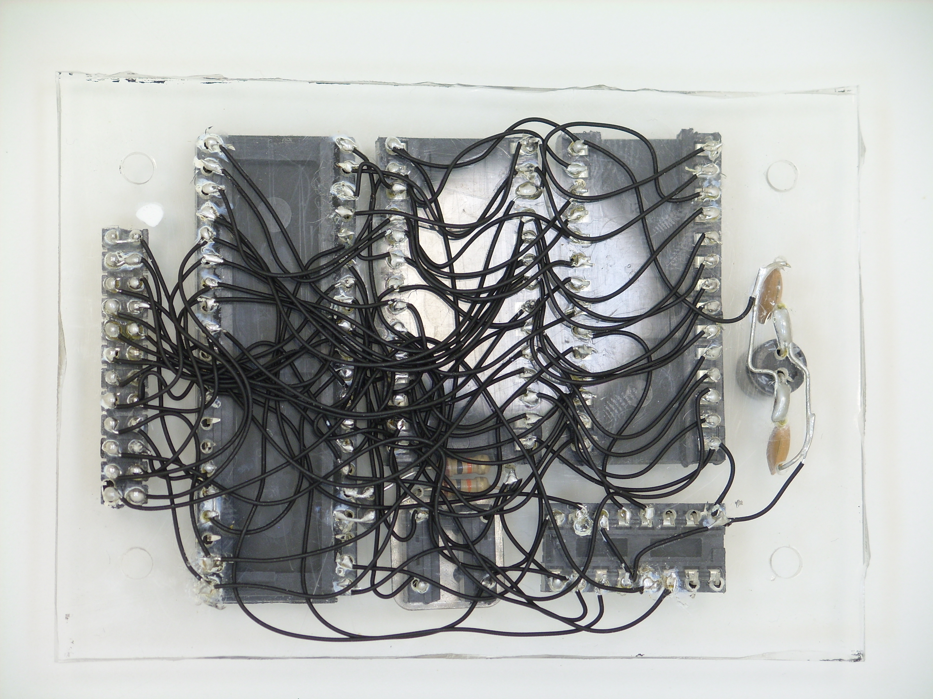
...and here's the back.
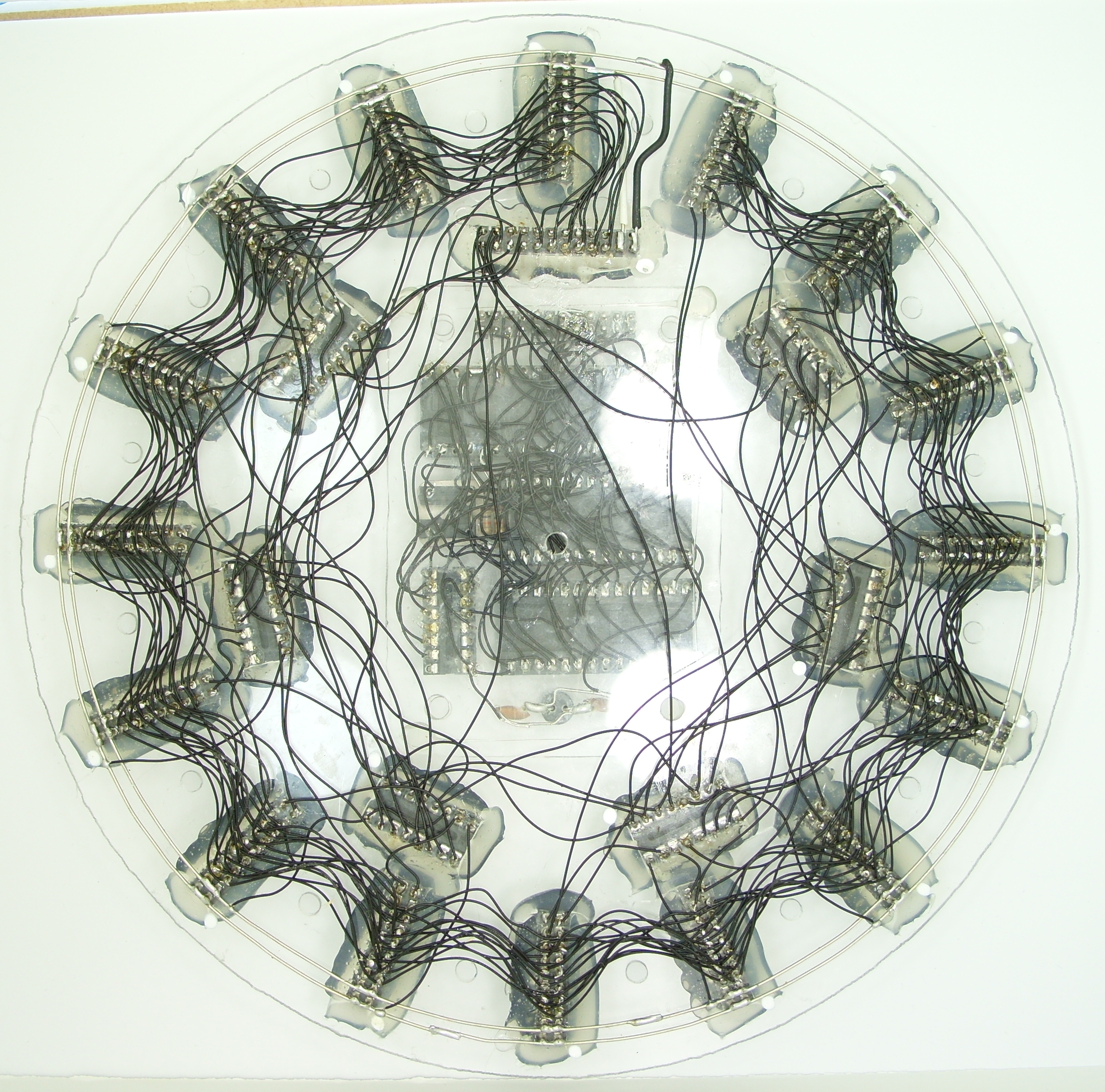
The acrylic glass is surprisingly resilient to being burnt or melted. I was afraid that would be a problem when I first came up with the idea, but I've never had it be an issue, even where I've had to do a lot of work to fix a circuit. It'll start to look kind of bad after enough heat, but remains structurally sound which is all that I care about.
Eventually, out of boredom, I decided to make an EEPROM-programming Z80 on a proper circuit board. Since the circuit for the EEPROM-programmer is so complicated, I couldn't get it onto a two-sided board without a complete mess of traces which prevented a compact design. So I learned how to use the ATF22V10 programmable logic chip so that I could put all of the logic into one chip. That allowed me to make this:
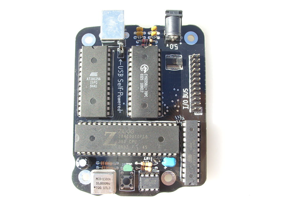
USB connector at the top for EEPROM programming, and an ATtiny13A bottom-center which performs power-on reset and reset when triggered by the programmable logic at bottom-right. The one surface-mount chip is the FT240X for the USB connection. The I/O bus connector connects to a bus board. It's cool, but other than test that it works, I never really did anything with it.
I never had a PCB made for the bus board. Any PCB over 10cm x 10cm is so expensive to have made, and within that size there's really only room for 3 or 4 expansion slots. I guess a smart design would figure out how to link two boards of that size together, by only populating the 3-to-8 decoders on one board and then connecting the two boards somehow.