Did I not post this?
It is kind of low-res, so maybe I just intended to take another photo later. I just noticed it in the
directory of junk posted to my blog.
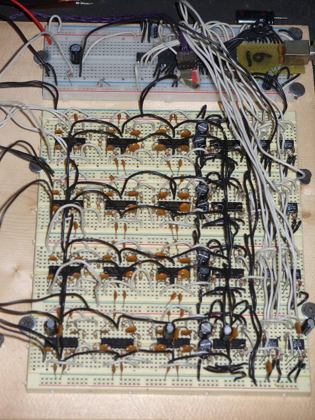
That's the eight channel version. Each row of solderless breadboard has four op-amp chips and two ADC chips. The top half of the op-amp chips does one channel, the bottom half the other. Each channel goes into its own ADC so that they can be sampled simultaneously. At the top is a AT89S52 connected to an FT245RL which connects to a PC.
I eventually decided the large number of filters weren't doing anything to help. So I reduced it from 6 low-pass filters to just 2 per channel, using one of each type shown in the schematic in a previous post, and keeping the high-pass filter unmodified.
Apparently there's more to making a highly selective filter than taking multiple not-so-selective filters and connecting them in series. (I'd assumed as much, but every description of how filters work describes them in a way that indicates this would work just fine, even though I can't imagine how that could possibly be so.) I found some web sites offering to calculate all of the component values, but after building the circuits, they didn't seem to work any better. Perhaps it's just because I don't have the exact component values indicated.