I made some fun PCB software. You draw tracks and it forms them out of little segments which it then optimizes by drawing them as tightly together as possible while keeping them as far away from everything as necessary. Way the hell nicer than EasyTrax which is what I was using before, and also KiCad which I've looked into on several occasions but just can't get past the point where I ask "why the fuck do I have to draw a schematic in order to create a PCB" and thus I don't know the first thing about how to use. In mine, no schematic is necessary. You place pads, then draw tracks, and then you're done. It even creates the board outline for you, once again by simply making it as small as it can be while maintaining proper clearance around everything. The only thing it doesn't do is silkscreen text, as you have to draw it all by hand, but it makes for an interesting effect I think.
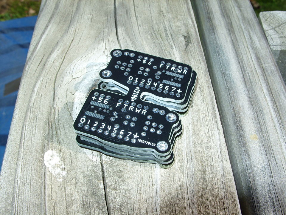
So I made a new break-out board for the FT240X, since my old one was a bit large, and I wanted a version where the USB connector is on the left instead of the right. Since DirtyPCBs has no issue with panelized designs, I put both into a single PCB which I could order for $14.
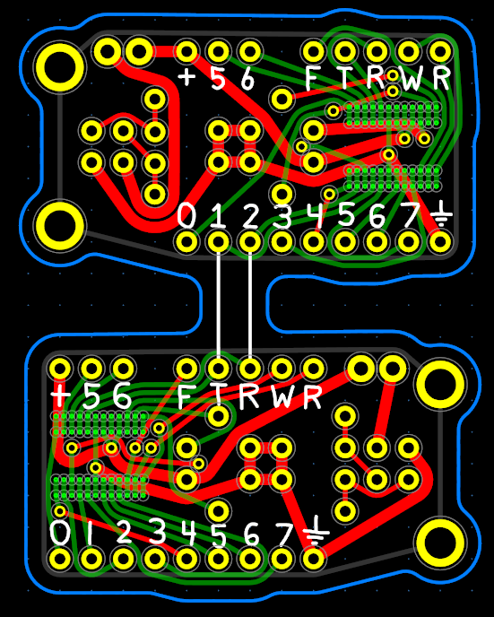
While most people put little perforation holes between the boards so they can be easily broken apart, I don't like the way this looks, mostly because DirtyPCBs is seemingly incapable of doing non-plated holes. So I decided I'd just slice the boards apart with my Dremmel's diamond-coated cutting tool since I could make it nice and smooth that way.
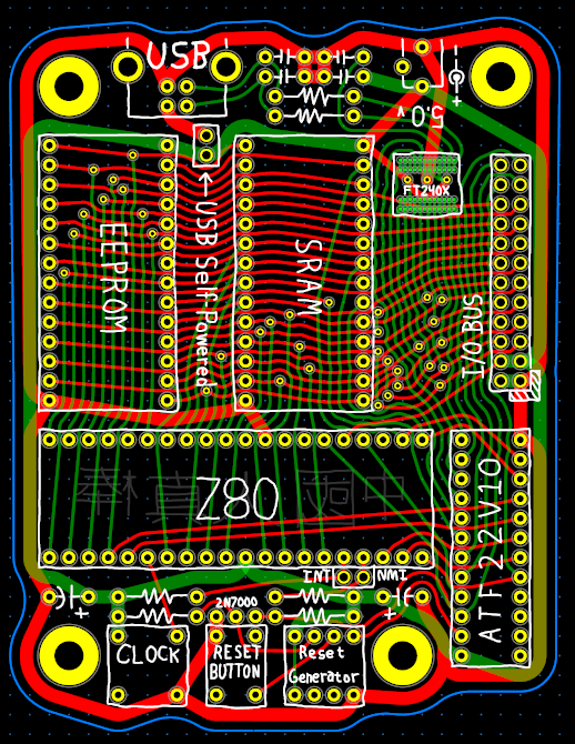
I also made a Z80 board. I decided I wanted to do
my Z80 EEPROM programmer, but found that wiring all of the logic gates together was a total bitch. I did it, but was so displeased with the results that I looked into programmable logic and figured out
how to program the ATF22V10, as it was the cheapest programmable logic I could find. So then I designed the board with the ATF22V10 connecting everything together, and with an ATtiny13A performing as a reset chip. Since this board was larger, ordering it cost $25.
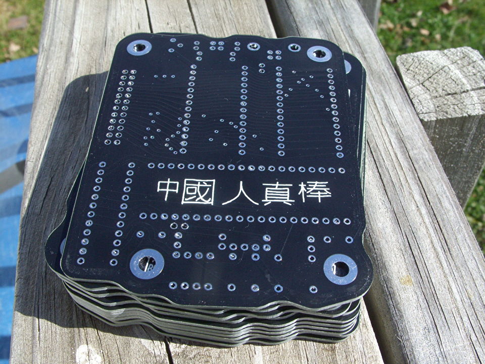
So I ordered them and 3 to 4 weeks later I received these:
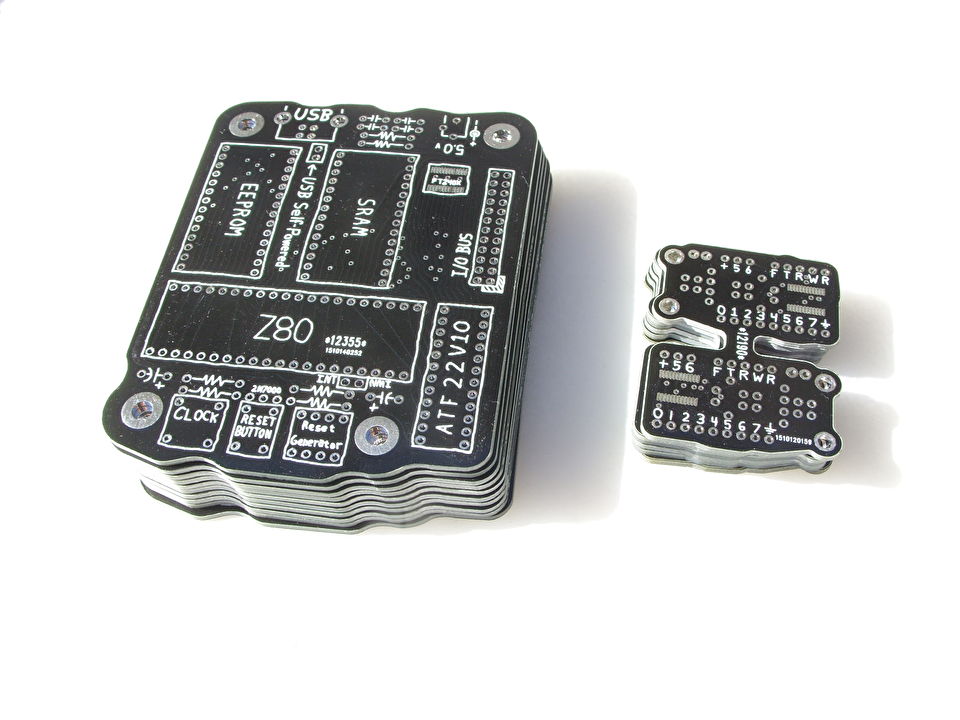
I got 11 copies of each board, so each FT240X board cost me 64 cents, and each Z80 board cost me $2.27.
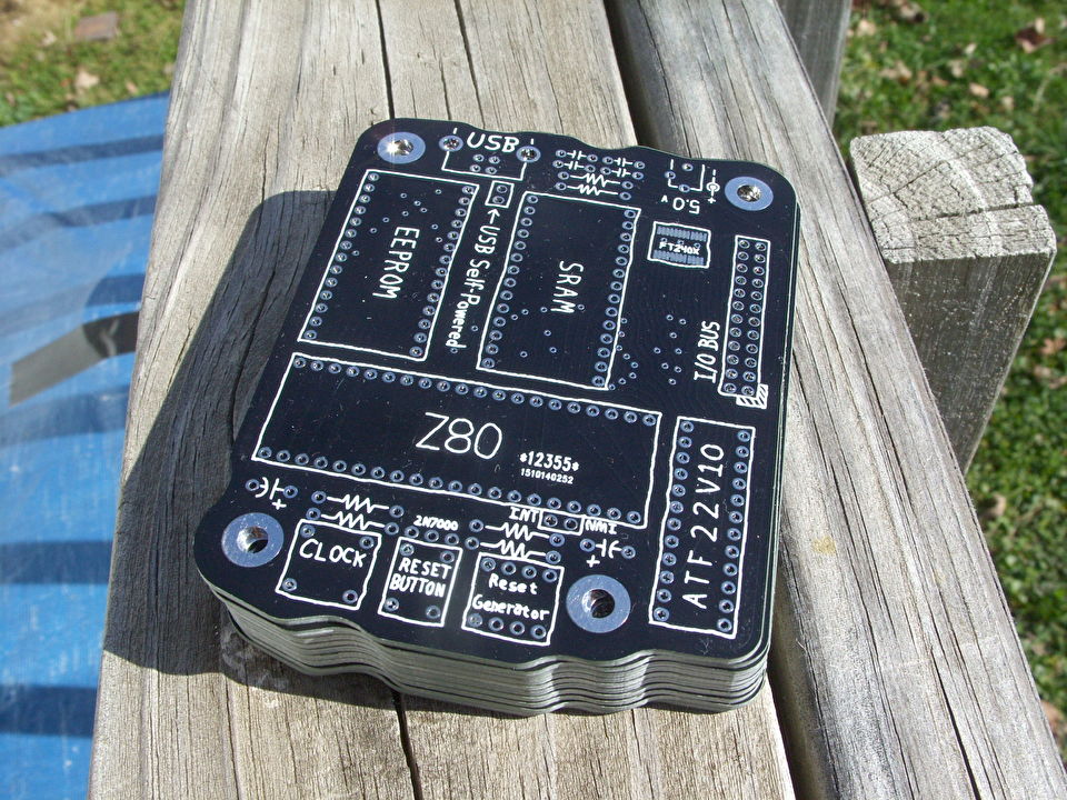
Here's some more pics on a more attractive wood background:
Here's the FT240X board populated with parts, along with my previous larger design:

The main issue with the old one was that it was so large that it didn't leave much room to connect wires above and below it. The new ones have more space above and below.
...and I just love that I have left and right versions of the board now. On one occasion I tried taking the old design and just turning it up-side-down. Despite realizing that all of the pin connections were now backwards, I still managed to attach power to it in reverse and fry the thing, and so I've been reluctant to try that again. However, these two versions have identical pinouts, just the USB connector is on the opposite side of the board, and so I don't have to worry about wiring them incorrectly.
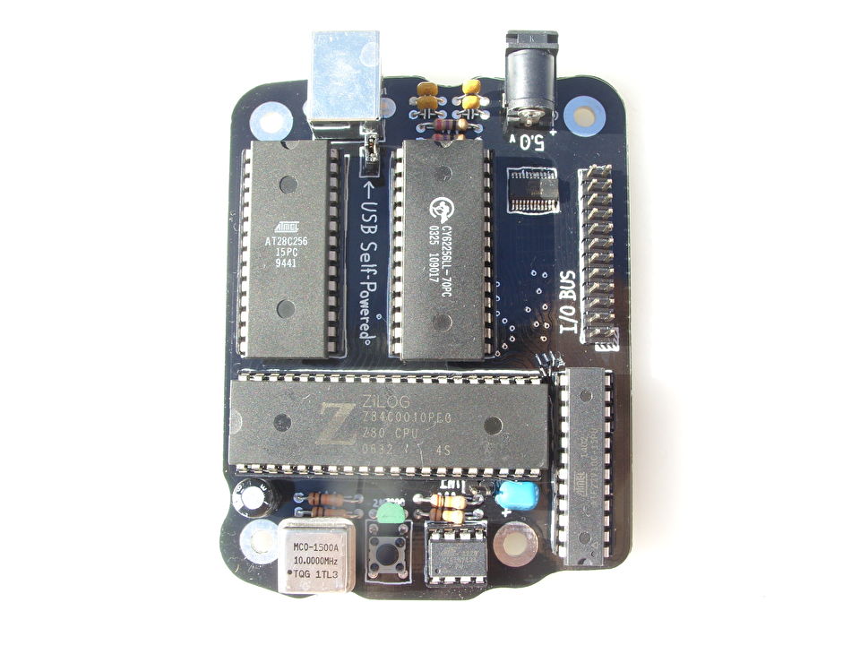
Here's the Z80 populated with parts:
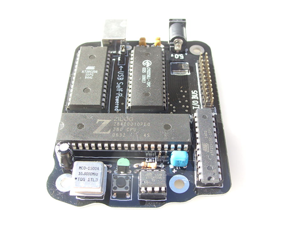
Unfortunately I made a few mistakes on this board.
The holes for the DC power connector are too small and spaced incorrectly. I noticed this the moment I looked at the boards, but strangely didn't notice when I printed out a copy of the board to see its size and test-fit the FT240XS on its pads. I should have test fit the DC power connector as well, but didn't. However I was able to make it fit by drilling two of the holes larger and removing the third pin (which is unused) from the DC power jack.
A few of the connections to the ATF22V10 are incorrect. Had I bothered to compile the code for the chip before ordering the boards, I would have realized it could never work the way I had it wired. So to make it work I had to cut three traces so that I could connect them to different pins, as well as connect two other pins together. You can see a few pieces of trace wire soldered to a few tracks between the Z80 and the ATF22V10 in the photo, though they then disappear under the socket of the ATF22V10.
Other problems include the screw holes not being exactly where I intended (top-left isn't aligned with top-right) though it doesn't matter as I have nothing it has to fit, and "USB Self-Powered" is a self-contradiction, as things are either "self-powered" or "USB-powered." That last one annoys me the most. It's like a typo that I can't correct.
Anyway, after those corrective efforts, the board does work. I suppose I could fix the design and re-order it, but I really have no clue what the fuck I'm going to do with this thing anyway. So to whatever extent that I really want more of these things, I think I'll just fix up the boards I already have and use them. The repairs don't really take that long to make.