I started working on a new EEG circuit like a month ago.
My previous EEG had two electrodes for each input channel. (As does the OpenEEG project, which I despise.) This time I wanted to create an EEG which had multiple electrodes with a common reference. I also wanted to test my filter designs in the same way that I tested the Zeo's filter, to make sure they were as optimal as I could make them.
I realized that, rather than send the test frequencies through one at a time as I did when testing the Zeo, I might just as well send them all at once in one signal. After all, the whole point of Fourier analysis is to separate the frequencies.
So here's a screen capture of the filter test program:
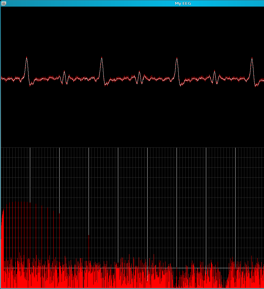
The top half is just the display of the test waveform, the white being the filtered signal, and the red behind it the unfiltered signal. As you can see, there isn't a whole lot of 60 Hz left in there after the hardware filtering.
The bottom half is a frequency analysis. The vertical bars represent integer frequencies, with 0 being on the left, and the brighter vertical bars marking each 10 Hz interval. The horizontal bars are a logarithmic scale, with each line representing a two-fold increase in signal strength, and the brighter line near the bottom representing a 0-bit input signal, and the line above it a 1-bit input signal (in other words, just barely detectable, and likely in the error range of the ADC).
The test signal contains every frequency from 0.1 to 1.0 Hz in 0.1 increments, then 1.0 Hz increments up to 10 Hz, then 2.0 Hz increments up to 20, then 10 Hz increments up to 60 or something.
The peak response is somewhere around 7 Hz.
I was hoping to allow more DC to pass, but decided there was a limit to how long I was willing to wait for the DC filter to adjust when I move around (a few seconds, rather than a minute), and thus decided that 0.7 Hz being half the amplitude of 7 Hz was good enough. After all, I can always scale the values by their known attenuation when doing frequency analysis.
For the higher frequencies, it turns out that my desire to pass everything up to 30 Hz unaffected, while filtering 60 Hz to a great extent, is quite difficult. I ended up using a 2-pole butterworth filter, which I then built six of and connected them in series.
Here's the schematic:
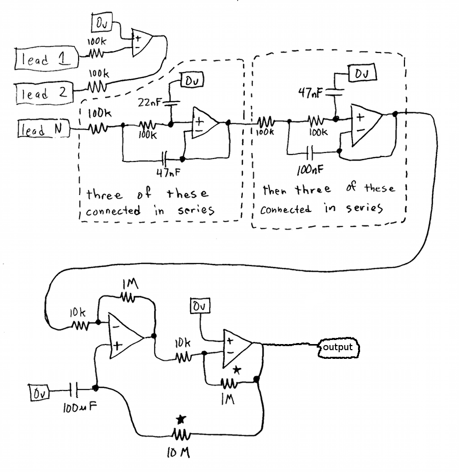
All of the op-amps are TL084, which feature JFET inputs, meaning that the require essentially no current from their inputs. You could probably get away with using other op-amps. The TL084 is just my favorite.
Not drawn is the power supply, which I went all out on in order to remove the 60 Hz interference as much as possible without putting it on batteries. The power supply I used is an AC transformer, connected to a large bank of capacitors and inductors, which then powers a high precision voltage reference and some op-amps which use that high-precision voltage reference to switch some transistors to maintain a constant output voltage. You might just want to use batteries. It's a lot easier if you don't mind the hassle of recharging them.
The low-pass filter design came from
Filter Design in Thirty Seconds. I took the low-pass filter in that document and built six of them to use end-to-end. This was necessary because the 60 Hz interference is often much larger than the signal that I want to see, and I want it to be much smaller, but there's only about a factor of 3 between the frequencies I want to see and the 60 Hz which I don't want to see.
I probably should have given the notch filter a try. Maybe later.
The amplifier consists of two inverting amplifiers (see
Op-Amp Circuit Collection) connected end-to-end, such that the end result isn't inverted. Each amplifier amplifies by a factor of 100, for a total of 10,000. The reason for using two amplifiers is that the non-inverting amplifier doesn't draw current from the ground reference on its positive input, which allows me to substitute a voltage stored in a capacitor which is charged via a resistor to the voltage of the output of the amplifier. Thus, if the (average) output becomes high, the capacitor voltage becomes more positive, offsetting the high input voltage and causing the output to move towards zero.
The first two leads are for the DRL, an idea I stole from OpenEEG. Basically, the problem is that your body floats at some random voltage, which you can't simply offset with a differential input because it's often a voltage too high or too low for the inputs of your amplifier (like +/- 50 volts). ...and while you can connect a ground wire, doing so has two disadvantages: One is that you now have a low-impedance ground connection to your body, which means if you touch anything electrically charged, you now get shocked, rather than the usual case where you have to touch something electrically charged and something else that is grounded. The other disadvantage is that, at the very small millivolt scale at which we're trying to measure voltages, even the small impedance of that ground connection means that very little current will flow through it to correct the offsets in your body's voltage. So a simple ground connection doesn't completely solve the problem. The DRL circuit solves these problems by using one lead as an input to an infinite-gain inverting amplifier, which then feeds another lead. Because even small differences in voltage are amplified to full scale, the problem of too little current flowing is solved, and because of that, the connection no longer needs to be low-impedance in order to guarantee that your body is maintained at the correct voltage. The two leads aren't completely wasted: While the DRL output can't be used for anything because the signal there just looks like noise, the input is held at zero volts by the DRL circuit, and thus is the reference point for all other inputs, but as it's always zero volts, you don't actually need to feed it to a ADC.
Thus, the schematic as drawn shows only one lead for the input. It's still a differential input, as it represents the voltage as referenced from lead 1. It's also possible to simply average together all of the N inputs, and use that average for the DRL input. In the case of an EEG, this creates an artificial input, presumably somewhere in the middle of the brain, to which all other inputs are referenced. I'll probably wire it up like that eventually, but for now I only have the one input channel, and I can't reference it to an average of itself.
Anyway, here's an example of it at work:
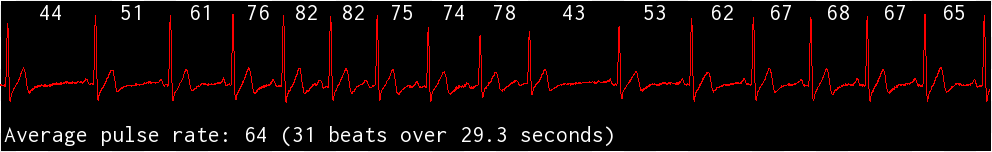
The number between each pair of beats is the "beats per minute" for that interval, if that interval were repeated for a full minute.
Have to love those irregular heartbeats. This was recorded about 30 minutes after a quick 5 minutes of vigorous exercise. Before that, it looked similar, but didn't go up anywhere near 80. Probably more like 60 with the occasional 40, in as much as I remember. I decided to try some exercise to see if the problem went away, and it did, even after resting, until I sat up.
I was reading some junk on the internet the other day that was making me think I have hypothyroidism. The evidence is slim, however. ...but that irregular heartbeat makes me wonder even more. It's like it just wants to beat slower, then once it does, decides that's too slow. I did drink a cup of coffee today. I'll have to avoid caffeine tomorrow and see how it looks the day after that.
...and speaking of avoiding caffeine... I've found that, rather than consuming a tiny amount of caffeine, consuming none at all seems to help my sleep the most. However, despite all of my testing, I don't feel any better for it. I wonder if I'm just trading one problem for another, like with caffeine I wake up every time I can't breathe, but without it, I continue to sleep and suffocate. I guess once I finish this EEG I can compare caffeinated sleep with decaffeinated sleep and see what the difference is.